Balloon Tracker Stefan v2
Division into parts
I will split the post about this tracker into 3-4 separate parts:
- assumptions, hardware
- software architecture
- SX1278 - how to modulate “anything” on it
- implementation of SSTV, AFSK + APRS, 4-FSK + Horus
We’ll see how much content comes out of this in practice - some things might merge, others might split.
The beginnings and what happened to version v1
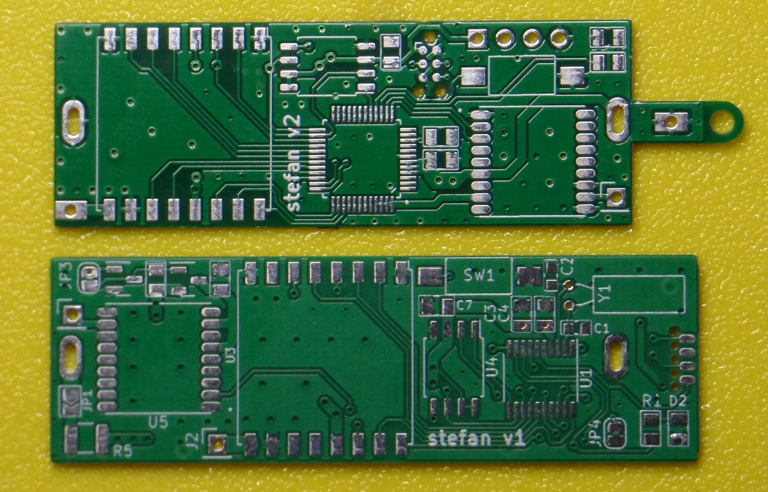
Version v1 was officially a tracker for a cat named Stefan, but the device turned out to be too big, too heavy, and due to several hardware errors, it didn’t work. So I left the cat alone, and the idea to adapt it into a balloon tracker was born.
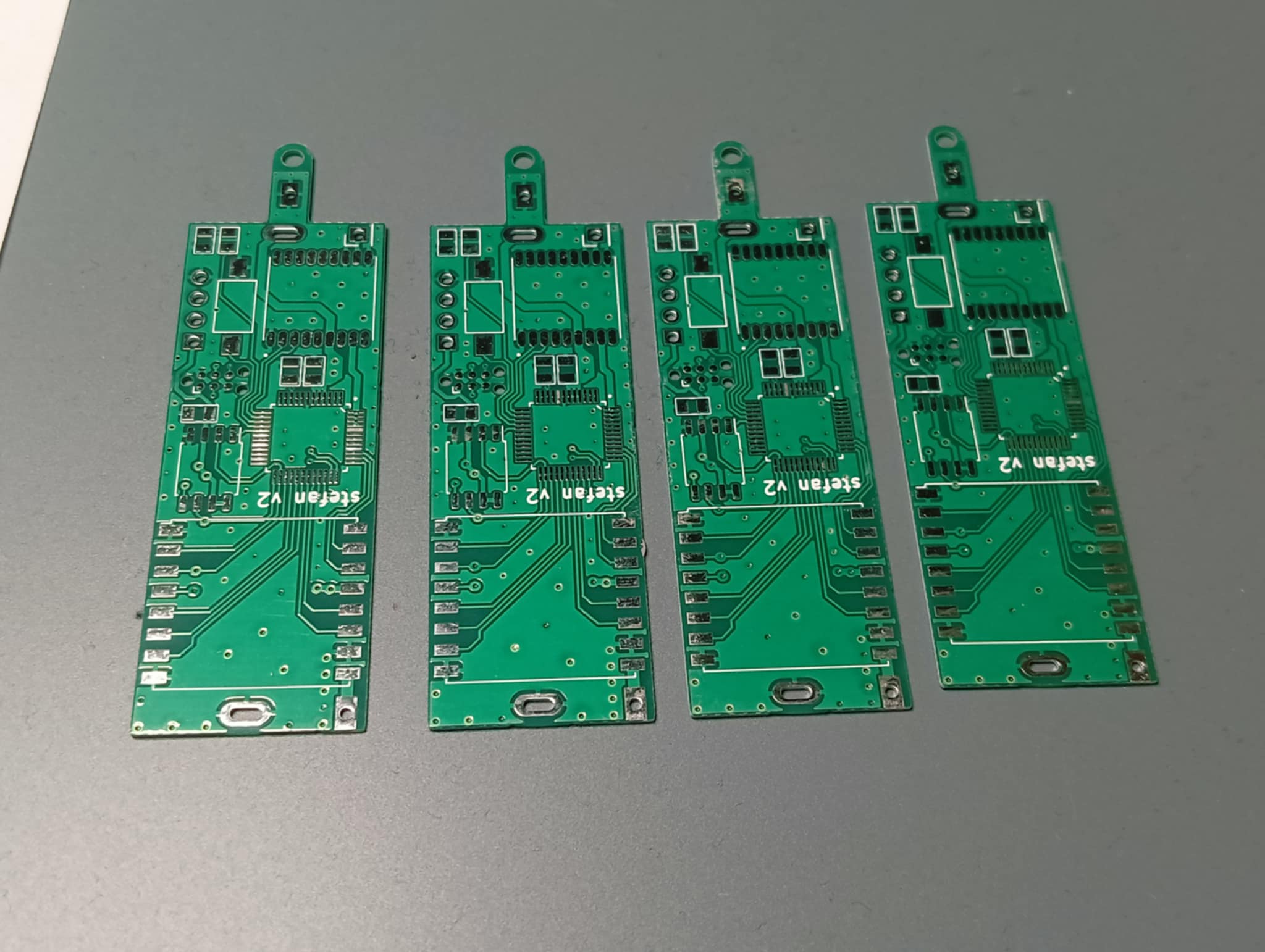
From what I can see in the repositories, the project was started over two years ago. I only managed to preserve the software repo - the hardware, made in KiCad, was lost with my old laptop. I was only able to recover the gerbers from the PCB production order :p
evolution of assumptions
precise time measurement, RTC → imprecise measurement
v1
The initial idea was to periodically send the position to a gateway based on similar hardware, hence the place on the PCB for an LSE (Low Speed External oscillator), which was supposed to drive the RTC peripheral more stably than the internal oscillator built into the microcontroller. On the board photo, it’s marked as Y1.
For monitoring purposes, the device would wake up once every 24 hours and send a frame: “I’m alive, my battery voltage is X.XX V”. Of course, to allow locating “at any moment”, listening was running all the time using sampled RX (a technique called preamble hunting - allowing the receiver’s current draw to go below the values declared in the documentation for continuous RX; I think that could be a topic for a separate post).
The internal LSI oscillator is quite unstable - in my tests I got an error of around ±20 minutes per day. After a week, the time measurement drift could exceed 2 hours. Without frequent synchronization, LSI is disqualified from this type of application, which is why a more accurate external oscillator is present on the PCB.
v2
In the balloon tracker, however, this assumption didn’t matter much - we want to transmit packets fairly often, and if we scale the error to a shorter interval - e.g., sending position every 5 minutes - the error from the internal oscillator would be around 4 seconds at most. So on the v2 board, there is no external oscillator.
power efficiency
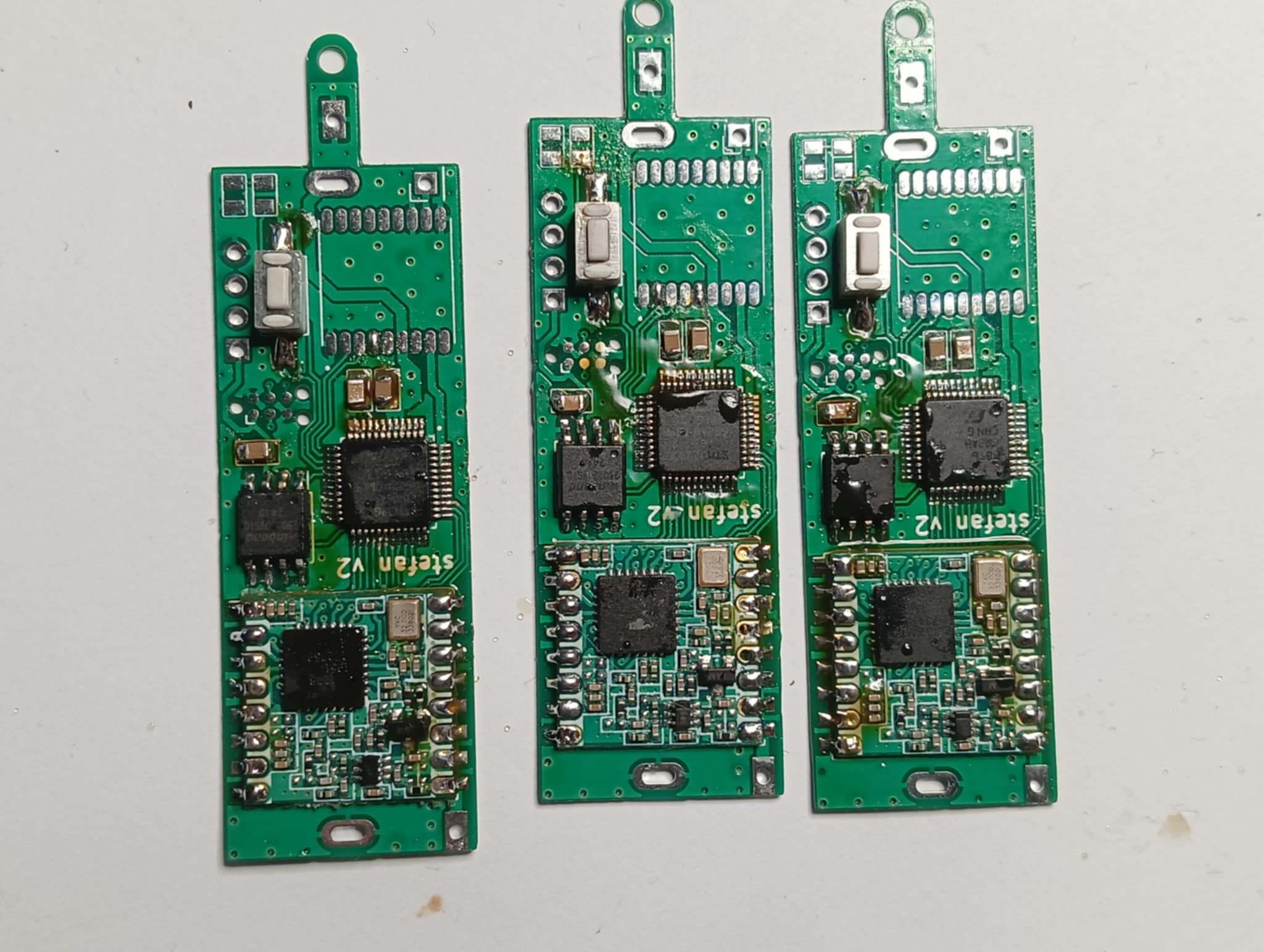
When the device is idle - e.g., waiting to send the next frame at a given interval or performing sampled reception - the processor should be in sleep mode, the GPS powered down, and the radio module configured to draw as little current as possible. On the v1 board, the GPS (U5) is switched by a MOSFET in a high-side switch configuration. In v2, the GPS is powered directly from four GPIO pins of the microcontroller - fewer parts to solder.
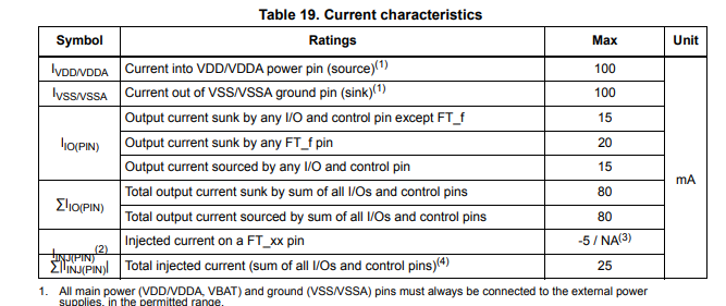
The 4 pins I used to power the GPS are marked in the documentation as FT_f, so in theory, they can output a total of 80 mA, leaving 20 mA of headroom for other currents drawn from the microcontroller. That’s more than enough to power the GPS, which - based on my measurements - used a maximum of 28 mA while searching for a position.
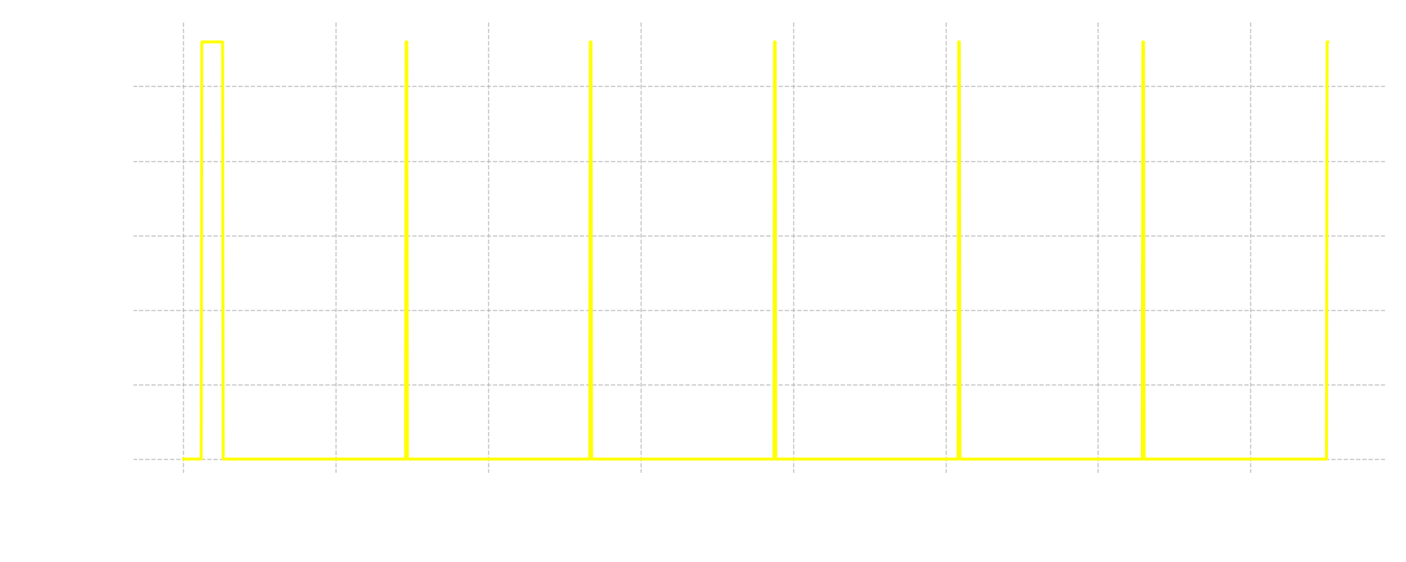
Most GPS/GNSS modules support hot/warm start, which allows them to acquire a position very quickly, provided the previous position fix happened recently. These modules have a separate power line that maintains the RTC and memory storing information from the last fix. Thanks to this, when we’re not using the GPS, we can cut off its main power and keep the RTC powered through a separate pin. This standby mode consumes significantly less current than when the GPS is fully powered.
Thanks to this mechanism, a lot of energy can be saved. For example, let’s consider a scenario where the position is transmitted every 5 minutes:
- first GPS fix: 35 seconds of GPS power
- turn off the GPS, transmit the frame, put peripherals to sleep and sleep for ~5 min
- second GPS fix: ~2 seconds of GPS power - and we get the position thanks to hot fix
- turn off the GPS, transmit the frame, sleep for ~5 min
- third GPS fix: ~2 seconds of GPS power (hot fix)
- and so on…
To illustrate what the current consumption of the GPS looks like in the above scenario with hot fixes:
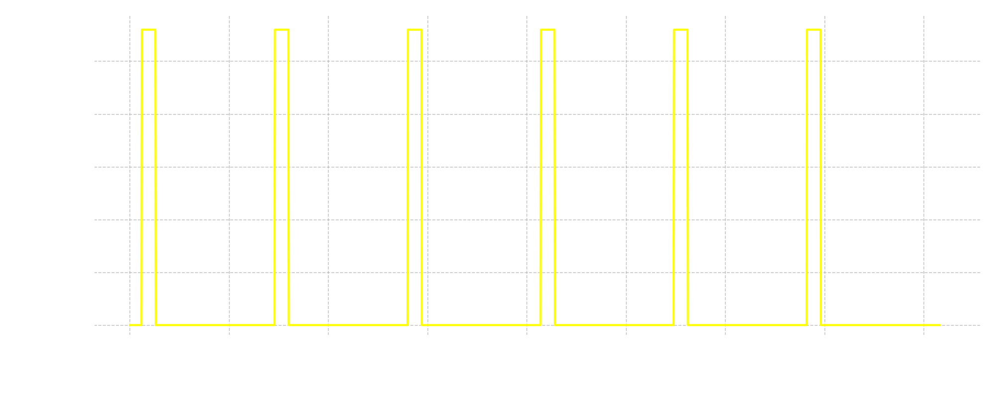
In the v1 board, the MOSFET switch powered both the GPS main line and its RTC backup pin, so the hot fix functionality didn’t work. As a result, every time a position fix took over 30 seconds.
Current consumption of the GPS without a working hot/warm fix:
v2 includes a fix: the backup pin is powered continuously from the main power line.
Archiving -> storage for SSTV
In v1, I installed an external flash memory to archive all acquired positions. In v2, the positions are transmitted in real time, almost always within range of APRS receiving stations. So I decided that archiving wouldn’t be necessary, but the flash memory will still be useful as storage for SSTV images (more about image encoding and SSTV transmission in future posts).
Components
Microcontroller
The brain of the entire system - I chose the STM32G030, at that time the cheapest and most available 32-bit microcontroller from STMicroelectronics. It runs on an ARM Cortex-M0+ core, with a maximum clock of 48 MHz. 8 KB of RAM, and depending on the version, 32 or 64 KB of FLASH memory.
And most importantly - the processor supports several sleep modes while retaining all RAM and CPU registers, which allows the program to continue running after wake-up with no extra steps.
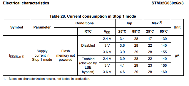
At room temperature, Stop 1 mode reduces the microcontroller’s current draw to under 5 µA.
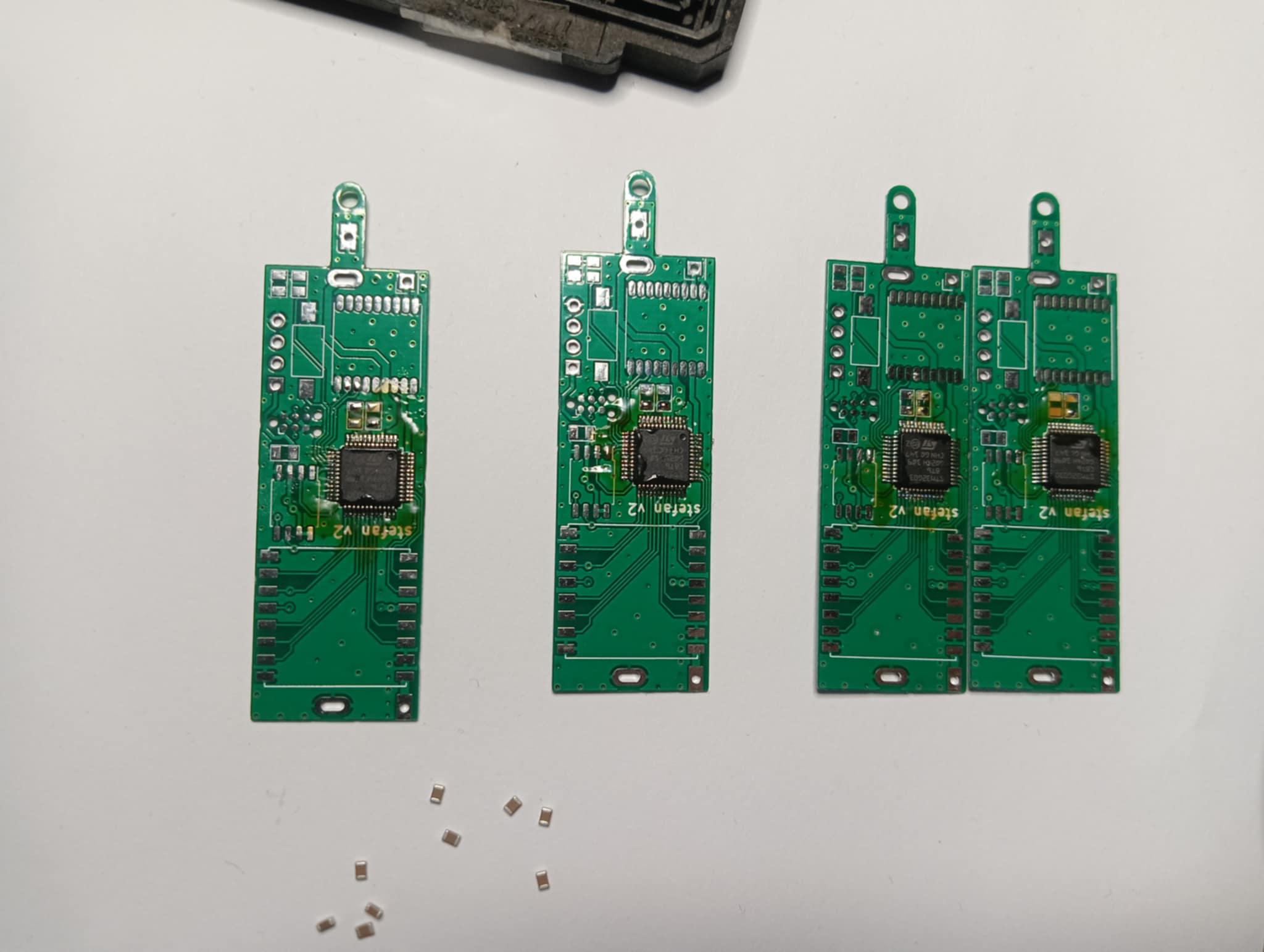
In PCB v1, I used the TSSOP20 package - 20 pins, fairly easy to solder. However, this version only has 32 KB of FLASH. During experiments with SSTV, AFSK, AX.25 + APRS, the program barely fit in memory. In v2, I used the 64 KB version, in an LQFP32 package.
Radio
The SX1278 - a chip from Semtech - supports 2-FSK, 2-FSK with Gaussian filter, OOK, and LoRa modulation in hardware. It operates in the frequency range from 137 to 525 MHz. It’s quite cheap - you can order a small board from China with the chip and RF frontend (filters, matching, RX/TX path) for 10-20 PLN.
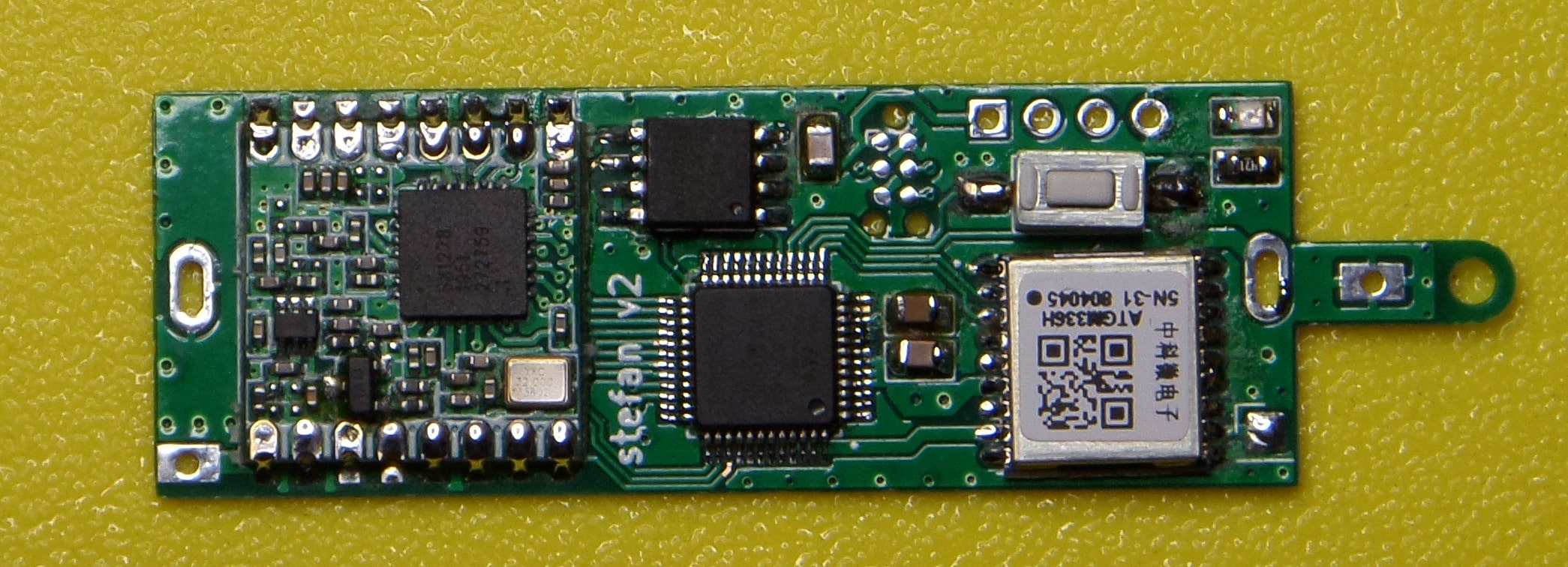
GPS
The boards have a footprint for the ublox M10 module. Many GPS modules from different manufacturers fit this footprint. I tested with Quectel L-70 and Chinese ATGM336H modules.
Power supply
There are basically no power supply components - no voltage regulators or DC-DC converters. The device is designed to run directly from 3.6 V lithium batteries in a 1S configuration. All components work fine throughout the voltage range of these batteries. I think the only thing that might be missing - and isn’t there - is reverse polarity protection for the battery :D.
Soldering time